Fluffy McDeath's Arduinory
The RGB LED and a GUI
The other day I dropped by my local (across town) electronic parts store and noticed they had a bag of RGB LEDs on the wall, five for $3.50. I remember when those things were about six bucks each so, for no good reason, I bought a bag.
When I got them home and started playing with them the first thing I noticed is that while the part contains a red LED, and green LED and a blue LED the colours don't really merge as the individual light sources are not mounted particularly close together and the plastic enclosure is so clear that the point sources are clearly visible and most of the light escapes without scattering making the RGB LED look pretty dark. To scatter the light I wrapped the RGB LED in some white tissue paper and that seemed to help a lot in mixing the red, green and blue and giving a nice vibrant something something.
Once I'd tried lighting this thing up manually I wanted to hook up the Arduino and use pulse width modulation (PWM) to control each colour so I could produce a rich range of colours. I used an UNO board so you will have to make the necessary adjustments if you are using something else but I hooked up the RGB LED like this.
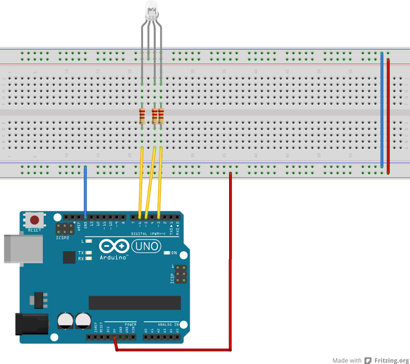
What we have here is the three colours hooked up to PWM pins 6,5 and 3, each through a 220Ω resistor (red, red, brown) and then the common anode is attached to the +5V rail. If your part was common cathode then you would hook up the common to GND. There would also be a small change in the python script I'll note later.
The sketch I used is shown below. If you hook up your red, green and blue pins in a different order you can just change the pin numbers to the ones you used (const int rPin, etc). When I was poking about on the internet looking to see what might be best practice for getting strings from the serial I saw a lot of examples of fairly convoluted and tortured code to Serial.read() a character at a time, which could be justified if you needed to make sure your sketch was getting to do something important in between characters, but my sketch was just waiting for strings and then processing them so I used Serial.readBytesUntil() instead. This method reads bytes into an array until a certain charcter is received or the specified maximum number of characters have been received. I'm using colons (:) to delineate my strings. You could just as easily use newlines to delineate your strings (read until '\n') and then set the Arduino serial monitor to send newlines when you hit return. However, I didn't - and I used a python script to talk to the Arduino.
/* rgbDiode with Python UI providing input to serial */

/* Pin numbers for the different colours */
const int rPin = 6;
const int gPin = 5;
const int bPin = 3;

void setup() {
  // set the digital pin as output:
  pinMode(rPin, OUTPUT);
  pinMode(gPin, OUTPUT);
  pinMode(bPin, OUTPUT);
  Serial.begin(9600);
}

int r=0;
int g=0;
int b=0;
char buffer[10];

void updateRGB() {
  switch(buffer[0]) {
    case 'r': r=atoi(buffer+1); break;
    case 'g': g=atoi(buffer+1); break;
    case 'b': b=atoi(buffer+1); break;
  }
}

void loop()
{
  int count;
    // set the LED with the ledState of the variable:
    analogWrite(rPin, r);
    analogWrite(gPin, g);
    analogWrite(bPin, b);
    count=Serial.readBytesUntil(':',buffer,10);
    buffer[count]='\0';
    if (count) {
      updateRGB();
    }

}
Once you've got that sketch up and running on your Arduino make sure that you don't have the serial monitor open (in the Arduino IDE) because you are going to need to use the serial channel for python to communicate with the skecth. I'm presuming you programmed your Arduino over USB. You need to keep the USB connected for this part to work (obviously?)
You should "ls /dev" to find out what tty to use. In my case ttyUSB0 was the correct device to connect to my Arduino. If that's yours too then you can leave the "ser = serial.Serial('/dev/ttyUSB0', 9600, timeout=1)" line as it is, else you should change the device string to the one that you will be using.
Here I will mention what I alluded to before and that is if you have a common cathode device then you need to make a change in "callback". For a common anode device, the LED is on with a logic high, for a common cathode device it is on with a logic low. That means that, when using PWM which will control the LEDs brightness by switching between high and low quickly with different amounts of time for each state. If you are using common anode then the brightness increases the more time the PWM is low. With common cathode it's the reverse. A value of 255 for an analog write on a PWM pin will spend all of it's time high and for a common anode part that will mean off. That is why I subtract the slider value from 255, so that a slider value of 0 will turn the LED off. If your part is common cathode then instead of "outstr=str(event.widget.ID)+str(255-event.widget.get())+':'" use "outstr=str(event.widget.ID)+str(event.widget.get())+':'".
from Tkinter import *
import serial

ser = serial.Serial('/dev/ttyUSB0', 9600, timeout=1)

ser.write('r255:g255:b255:')


def callback(event):
	outstr=str(event.widget.ID)+str(255-event.widget.get())+':'
	ser.write(outstr)

def addSlider(ID, color):
	slider=Scale(root,from_=0,to=255,orient=HORIZONTAL)
	slider.bind("", callback)
	slider.config(length=256,troughcolor=color)
	slider.grid()
	slider.ID=ID;

root=Tk()
root.geometry('260x150')
addSlider('r','#FF0000')
addSlider('g','#00FF00')
addSlider('b','#0000FF')
mainloop()
Once you've save the python script as someting like "slider.py" you can now invoke it with "python slider.py" and if everything is working (and I don't recall but you may have to install a couple of python packages to get Tkinter or Serial but I don't recall having to do so on my machine), you will have a small window on your screen with three sliders, one red, one green and one blue. You can now change the RGB colours by moving the sliders on the screen! If your slider colours are not the same as your LED colours then just swap wires around until it's right.
And that's it. Not an epic app but kind of cute and "educational" illustrating RGB colours and a simple way to hook a UI to your Arduino.
This page uses ScriptHighlighter by Alex Gorbatchev